.16修改(3).png)


.16修改(3).png)
 Login
Login


Browse history
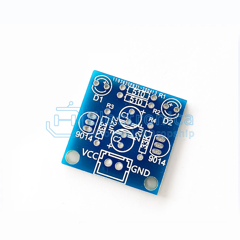
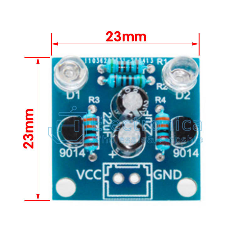
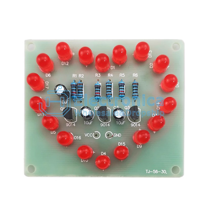
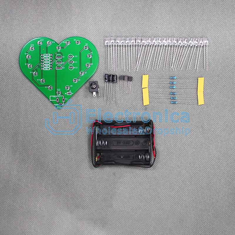
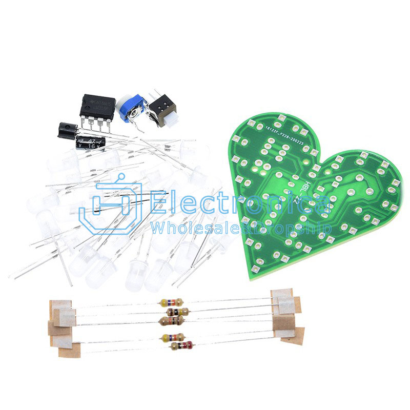
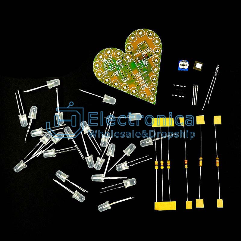
Description
After turning on the power, the left and right red LEDs (which can be replaced with other colored LEDs) flash alternately. After repeated cycles, the higher the power supply voltage, the brighter the LED. Changing the capacitance value of the electrolytic capacitor can change the speed of alternating flashing. The larger the capacitance value, the slower the flashing speed, the smaller the capacitance value, and the faster the flashing speed. The circuit is simple and easy to understand, and the solder pad has been treated with tin spraying technology, making welding easier and the solder joints more beautiful! Especially suitable for friends and students who are new to electronics
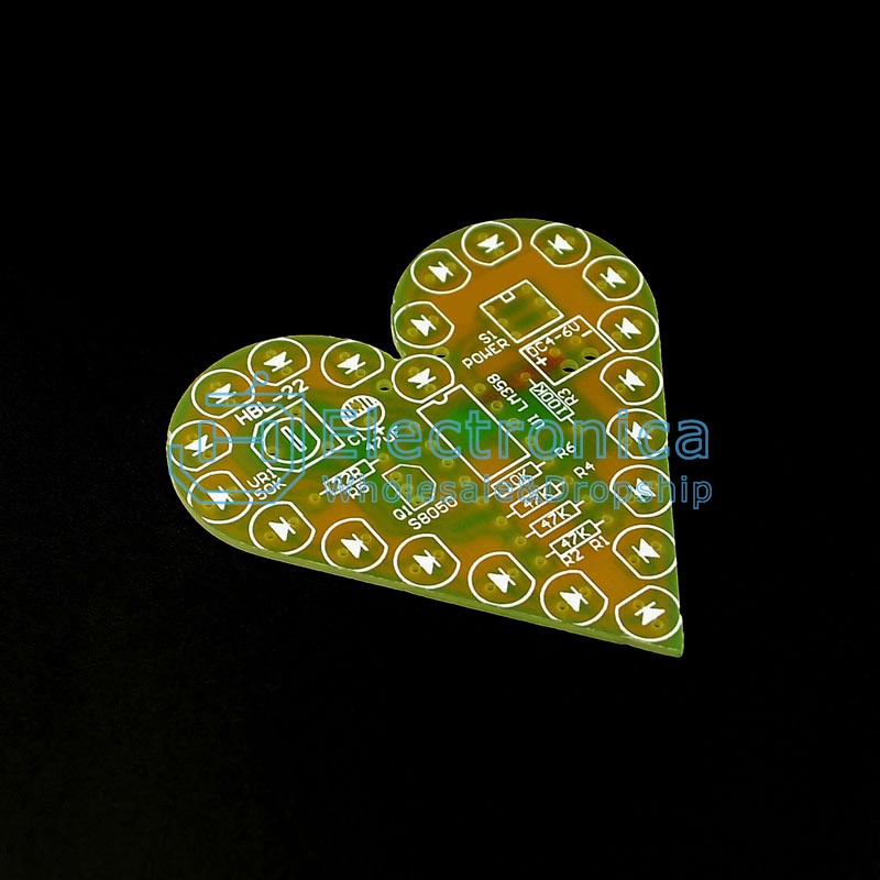
Circuit Principle:
As soon as the power is turned on, the two transistors must strive to conduct first, but due to differences in components, only one transistor conducts first. If Q1 is the first to conduct, then the voltage of the Q1 collector decreases, D1 is lit, and the left end of capacitor C1 is close to zero voltage. Since the voltage at both ends of the capacitor cannot suddenly change, the Q2 base is also pulled to approximately zero voltage, causing Q2 to cut off and D2 to not light up. As the power supply charges C1 through the resistor R2, the base voltage of the transistor Q2 gradually increases. When it exceeds 0.6 volts, Q2 changes from a cut-off state to a conduction state, the collector voltage decreases, and D2 is illuminated. At the same time, the decrease in collector voltage of transistor Q2 causes the base voltage of transistor Q1 to jump down through the action of capacitor C2, causing Q1 to change from conducting to cut-off, and D1 to extinguish. In this cycle, the two transistors in the circuit take turns conducting and cutting off, and the two light-emitting diodes continuously cycle and emit light. Changing the capacity of the capacitor can change the speed of LED cycling
Frequently Asked Questions:
Be careful not to solder the positive and negative electrodes of the LED incorrectly, with the long leg being the positive electrode
Be careful not to solder the wrong resistance value. The value with a green ring is 510 ohms, and the value with an orange ring is 33K or 30K
Be careful not to solder the positive and negative electrodes of the electrolytic capacitor incorrectly, with the long leg being the positive electrode
Be careful to avoid welding the transistor in the wrong direction and insert it according to the shape on the board
Pay attention to avoiding reverse power connection. The correct connection method is to connect VCC to the positive pole, GND to the negative pole, and supply a DC voltage of 3-12V
Pay attention to checking for short circuits and faulty soldering during welding
Package Type:
All goods will pack into cartons and wrapped full of waterproof tape before shipment.
We can accept customized package to meet different requirements:
1.Every item will separately pack into plastic bag,component,module can be packed in anti static bag.
2.Some fragile products such as the display screen can be packed in bubble bag.
3.Some large machines can be packed in wooden cases.
4.We can label JH code or client's code on package so that customers can check easily after receive goods.
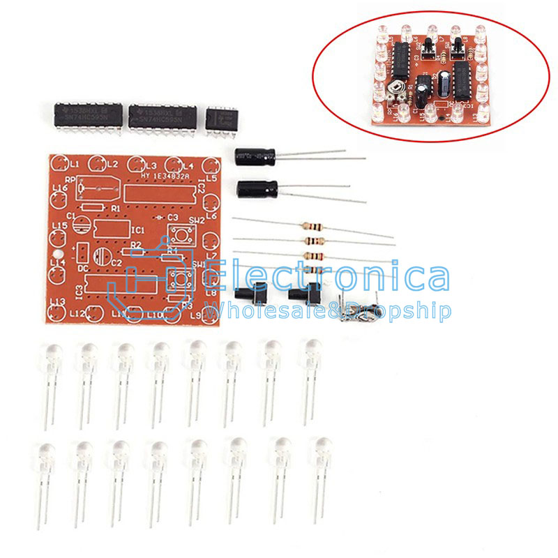
Flashing Circuit Module DIY Kit
SKU : YXC1213 Brand :


You May Also Like
NE555+CD4017 Flashing Water Lamp
$0.15
12pcs LED Circular Lamp DIY Kit
$0.12
Heart-shaped Flashing Light DIY Kit
$0.10
Electronic Windmill Water Flowing Light LED Kit
$0.95

Remote Control Music Butterfly Lighting Kit
$1.70
Voice Controlled Melody Light Kit
$0.65
4×4×4 3D Light Cube Kit
$5.15
16 Channel Water Flowing Lights DIY Kit
$0.83
Electronic Hourglass DIY Kit
$2.50
Heart Shape LED DIY Kit
$4.73
Automatic Energy-Saving Control System Kit
$0.22

Heart Shaped Flow Light Kit
$0.33
Colorful Heart Shaped Waterfall Light DIY Kit
$0.59

4×4×4 Colorful LED Cube DIY Kit
$2.91
Heart Shaped Breathing Light Kit
$0.54

Electronic Hourglass DIY Kit
$2.84
Heart Shape Breathing Light DIY Kit
$0.60
Triple Cycle Flashing Light DIY Kit
$0.21

NE555+CD4017 Red/Blue Strobe Flash Light DIY Kit
$0.60
Heart Shaped Breathing Light Kit
$0.54